Z-frame calibration
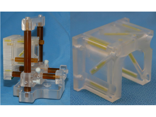
Z-frame is a calibration device that consists of a plastic enclosure that attaches rigidly to the template assembly (see figure below), and 7 elongated capsules containing liquid that gives bright signal in certain types of MR images.
Background
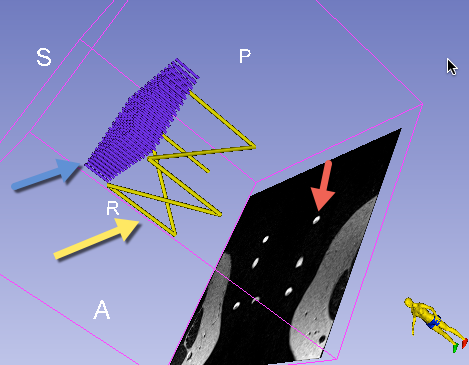
Given the known configuration of these capsules and their appearance in the ZFrame image, it is possible to align the known configuration with the corresponding image artifacts, and thus establish a transformation between the biopsy template and the scanner coordinate system.
 |
 |
|---|---|
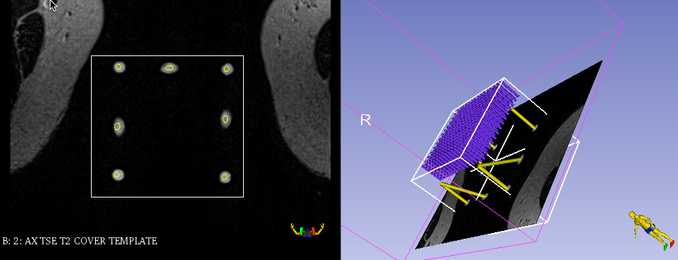
| Biopsy template assembly (left) and Z-frame. MR-visible capsules are yellow within a plexiglass enclosure. | Z-frame (yellow arrow) and needle tracks of the template (blue arrow) models before calibration. The red arrow points to the artifacts corresponding to the Z-frame in the ZFrame image slice. |
Workflow
Once ZFrame image is received, it will be automatically loaded and displayed. To perform Z-frame calibration, you need to define the region of interest (ROI) in the image corresponding to the location of the Z-frame artifacts.
After ZFrame image is loaded, ROI placement mode will be activated automatically, which is indicated by the ![]() cursor. Follow the steps shown below.
cursor. Follow the steps shown below.
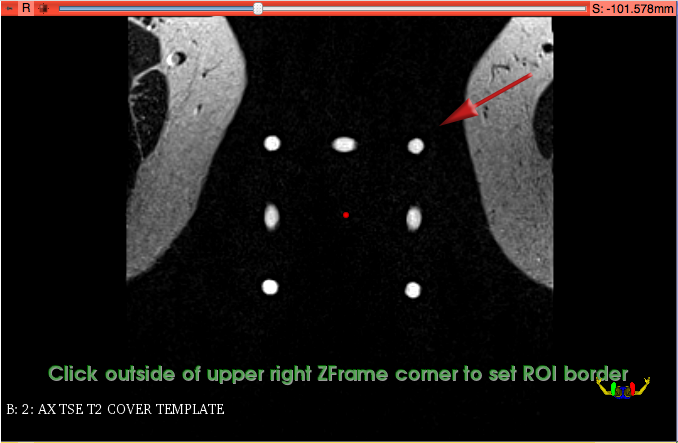
| Step 1 | Step 2 | Step 3 |
|---|---|---|
 |
 |
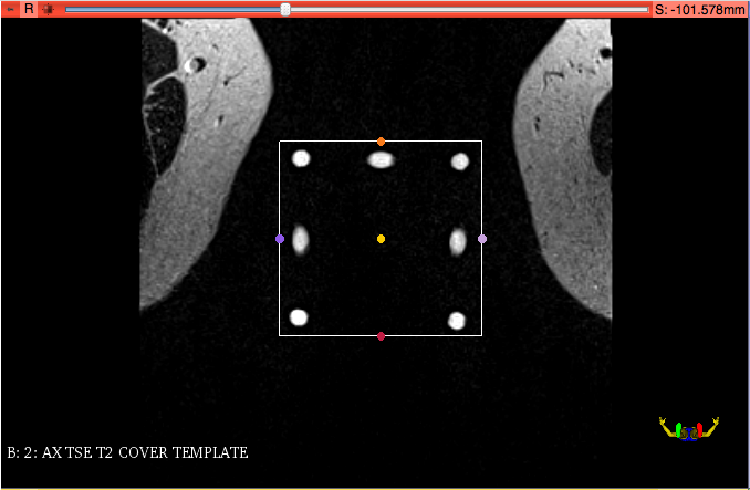 |
| Click once in the center of the group of bright dots corresponding to the Z-frame | Click once in the corner just outside that group | Make sure all dots are within the rectangular selection area |
After confirming that all dots are within the ROI, you will need to execute the Z-frame calibration by clicking "Run ZFrame Registration" in the module control panel.
Upon Z-frame calibration has finished, the 3D viewer will show the co-registered position of the ZFrame image.
IMPORTANT: Verify that Z-frame calibration was completed correctly by confirming the alignment of the Z-frame model with the Z-frame image artifacts, both in 2D and 3D views. In the 2D view, intersections of the Z-frame model with the image will be indicated by yellow outlines. Those must closely follow the bright artifacts of the Z-frame, as shown in the figure below. If you are unsure, please confirm with the clinical lead of the procedure!
In case of a Z-frame calibration misalignment see Correct Z-frame calibration misalignment
You must confirm registration accuracy by clicking "Confirm registration accuracy" button in the SliceTracker panel to proceed with the next steps of the workflow.