Correct Z-frame calibration misalignment
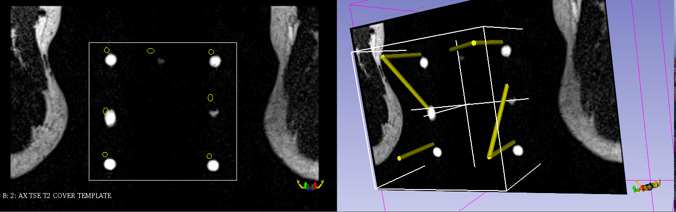
In case of the Z-frame model not adequately aligned with the Z-frame image artifacts, you will need to manually set the slice range where the Z-frame calibration runs on. The following screenshot shows such a misalignment.
 |
|---|
| Left: yellow outlines corresponding to the intersections of the Z-frame model with the image do not line up with the Z-frame artifacts. Right: 3D view confirms lack of alignment. |
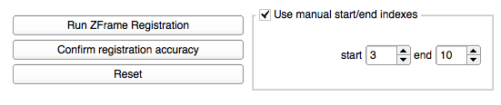
To set the manual start/end indexes, you need to check Use manual start/end indexes as displayed below.
To determine the index of the slice shown in the viewer, you can use the Data Probe module. In the lower left corner of the primary Slicer user interface, you see a collapsible button Data Probe. This module can be used to figure out the start and end index of the Z-frame image artifacts.
| Start index: | Scroll to the first slice, where all artifacts are clearly visible (7 white dots) |
|---|---|
| End index: | Scroll to the last slice, where all artifacts are clearly visible (7 white dots) |
The image below shows where to find the slice index of the current slice.
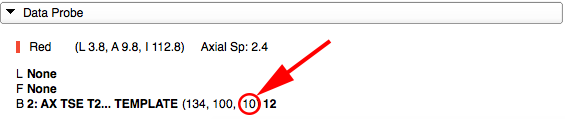
NOTE: Make sure to move the cursor within the current slice view, so that the Data Probe module gets updated according to it. The Data Probe module will only display values if the cursor is inside that slice view.
Once you are done with setting start/end index manually, click "Run ZFrame Registration" in the module control panel and continue with Z-frame calibration confirmation.